With a habitable volume of 210 cubic feet, the CM was the control center and living quarters for most of the lunar mission. The CM was 12 feet, 10 inches in diameter and 10 feet, 7 inches tall. At launch the CM weighed 12,250 pounds. The CM comprised three sections: the forward compartment; the crew compartment; and the aft compartment.
An ablative heat shield, made from a brazed stainless steel honeycomb with an outer layer of a phenolic epoxy resin protected the CM from the intense heat of reentry. During reentry the outer layer of the heat shield charred and melted, carrying heat with it. The heat shield covered the entire CM exterior and varied in thickness from 0.7 inches near the apex of the spacecraft to 2.7 inches at its base. Upon return from the Moon, the CM reached a speed of nearly 25,000 miles per hour. Entering the atmosphere at such a speed generated a lot of heat and the heat shield reached temperatures of 5,000° F.
The crew compartment contained three couches for the astronauts during launch and landing. The spacecraft commander (CDR) occupied the left-most couch. He operated the flight controls. The command module pilot (CMP) occupied the center couch; his primary duties included navigation and guidance. The CMP remained in the CM while the commander and lunar module pilot (LMP) descended to the Moon in the LM. The LMP occupied the right-hand couch.
The main display console in front of the couches contained the switches, dials, meters, circuit breakers and other instruments needed to control the spacecraft and monitor its performance. In general the left side of the panel contained flight controls; system controls could be found on the right side panels. The console was seven feet wide and three feet tall. Lockers that lined the walls of the crew compartment held food, water, clothing, the waste management system and other equipment.
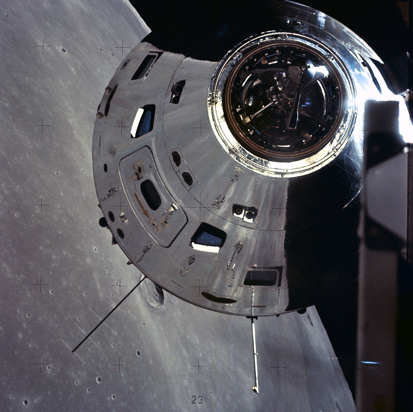
The surface of the moon is reflected in the command and service module as it prepares to rendezvous with the lunar module in this December 1972 image from the Apollo 17 mission. Image Credit: NASA
One of the improvements made to the CM after the deadly Apollo 1 fire in January 1967 was the development of a quick opening hatch. Apollo 1 incorporated a three-piece hatch that bolted into place. Even under ideal conditions opening the hatch required at least a minute and a half. Subsequent Block II versions of the CM had a single piece, hinged hatch that could be opened in seconds.
Other changes to the CM included removing flammable materials from the spacecraft. To further reduce the risk of fire, the cabin atmosphere comprised a nitrogen/oxygen mixture during launch. Once the CM was in flight, the nitrogen was purged from the cabin.
During flight, the life support system maintained a crew compartment atmosphere of pure oxygen at 5.5 pounds per square inch and temperatures between 70o and 75o F. Oxygen came from cryogenic storage tanks inside the Service Module. The same tanks provided oxygen for the fuel cells that generated electricity for the spacecraft.
A probe and docking ring topped the CM, near the apex of the conical spacecraft. The probe and ring assemblies let the astronauts dock with the LM. Once docked, the crew opened hatches in the CM and LM to move between the two craft. When the astronauts undocked from the LM for the last time following their return from the lunar surface, they discarded the probe and docking ring along with the Ascent Stage of the LM.
The forward compartment held two reaction control system (RCS) engines, three landing parachutes and two drogue parachutes. When the CM returned from space, the heat shield covering the forward compartment was jettisoned at 24,000 feet. Two 16.5-foot diameter drogue parachutes stabilized the craft until the three main parachutes deployed at an altitude of 10,000 feet. Each main parachute was 83.5 feet in diameter.
The aft compartment was around the periphery of the CM at its base. Twenty four frames divided the compartment into bays that held ten RCS engines, fuel, oxidizer and helium for the engines, water tanks, and crushable ribs to absorb the impact of landing.
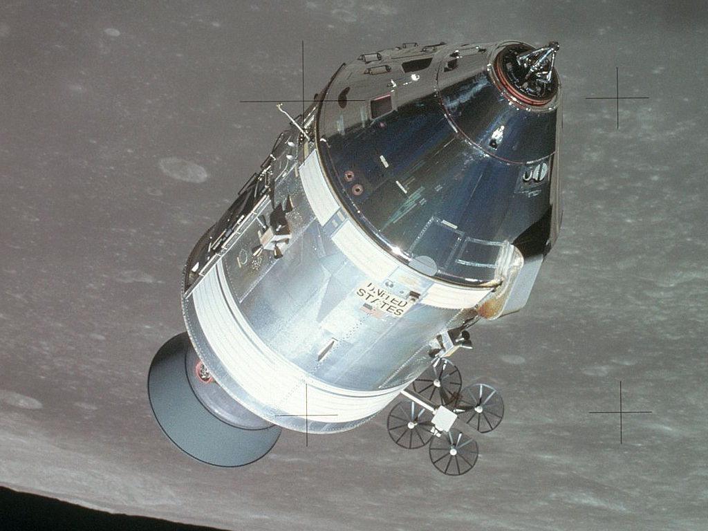
Apollo 15 command and service module in lunar orbit. Image Credit: NASA
The 12 CM RCS engines provided maneuvering after the CM separated from the SM just before and during reentry. Prior to reentry, the astronauts used the engines to maintain proper entry attitude; during reentry the engines controlled rolling. Each CM RCS engine produced a thrust of 93 pounds.
The cylindrical Service Module (SM) contained most of the spacecraft’s consumables and main propulsion system. The SM was 24 feet, 2 inches tall, 12 feet, 10 inches in diameter, and weighed 51,243 pounds at launch. It remained attached to the CM until just before reentry when it was jettisoned.
The Service Propulsion System (SPS) engine provided thrust for the braking maneuver to enter lunar orbit; “transearth injection” to head back home; and any major course corrections needed to refine the spacecraft trajectory. The SPS engine burned hypergolic propellants that ignited spontaneously upon contact to generate a thrust of 20,500 pounds. It could be restarted up to 50 times. Propellants for the SPS made up about 75% of the SM weight.
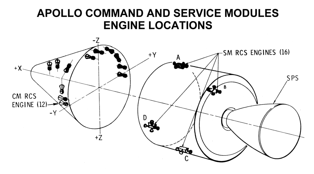
Image Credit: NASA
Four sets of RCS engines, arranged in assemblies of four engines each, provided thrust to maneuver the CSM in flight. Each SM RCS engine produced a thrust of 100 pounds. The RCS assemblies were placed 90o apart around the body of the SM.
Electrical power for the CSM came from three fuel cells housed in the SM. These combined hydrogen and oxygen to generate electricity. The fuel cells produced water as a byproduct. Each fuel cell generated 27 to 31 volts DC. Three silver oxide- zinc storage batteries powered the CM after separation from the SM.
A solid-propellant rocket motor on a tower topped the CSM during launch. This was the Launch Escape System (LES.) If the booster malfunctioned early in the flight, the LES would have pulled the CM away from the rocket, high enough for the parachutes to deploy. The LES was jettisoned at an altitude of 295,000 feet, about 30 seconds after the Saturn V second stage ignition. If the astronauts had to abort the flight after discarding the LES, they would have used the SPS.
Next month’s installment of the “Season of Apollo” will feature the 50th anniversary of Apollo 9, the first piloted test of the Lunar Module in orbit around the Earth.